Conectando um Servomotor
A servo is a small motor with a gearbox and control electronics. You can tell it what position to rotate the shaft to.
In iDryer-like devices, a servo can open a damper, move a small latch, press a mechanical switch, or redirect airflow.
The main mistake with servos: thinking it is a "small thing" and you can power it from any 5V pin on the controller. A servo can draw significant current, especially at startup, sudden movement, or when the mechanism binds.
Three wires
A typical hobby servo has three wires:
- power: usually
5Vor6V; - ground:
GND; - signal: control pulses from the controller.
Common colors:
- red - power;
- black or brown - ground;
- yellow, orange, or white - signal.
But you cannot blindly trust colors. Different manufacturers may use different color schemes. Before connecting, check the marking, product page, or datasheet.
Power separate, signal separate
The signal wire does not power the servo. It only tells the servo where to turn.
The servo draws energy from the power wire.
The correct logic is:
- the controller provides only the control signal;
- the servo is powered by a 5V/6V source that can handle its current;
- the controller ground and servo power ground are connected together.
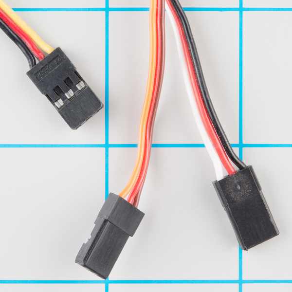
Source: SparkFun Electronics, CC BY-SA 4.0
Why you cannot power from weak 5V
Many boards have a 5V pin. This does not mean a servo can be safely powered from it.
When moving, a servo may draw much more current than its size suggests. If power is insufficient, typical symptoms appear:
- controller reboots;
- screen flickers;
- USB connection drops;
- servo jerks;
- Wi-Fi on ESP32 drops;
- servo hums but does not move;
- power sags at movement start.
For one small servo, board-supplied power sometimes works if the board and source are explicitly rated for that current. But for a real device with a damper, latch, or mechanism, it is better to use a separate 5V/6V DC-DC or power supply with a margin.
Common ground
If the servo is powered by a separate source, a common ground is needed.
Without a common ground, the controller and servo have no common signal level. The servo may not respond, may jerk, or may behave randomly.
Simple connection:
+5Vor+6Vfrom the power source goes to the servo power.GNDfrom the power source goes to the servo ground.- The controller's
GNDis connected to the same ground. - The controller PWM/GPIO pin goes to the servo signal wire.
Servo power and controller power may be different, but the ground must be common.
What signal is needed
A typical positional hobby servo is controlled by pulses.
Typical signal:
- pulse roughly every
20 ms; - about
1 ms- one extreme of the range; - about
1.5 ms- middle; - about
2 ms- other extreme of the range.
This is not typical PWM for LED brightness or fan speed. Here, pulse width in microseconds matters.
The actual limits of a specific servo may differ. Some safely operate not from 0 to 180 degrees but less. So extreme positions need careful testing.
Do not jam a servo against the mechanism
A servo tries to hold the commanded position.
If a damper hits the housing, an arm binds, or the mechanism reaches a physical stop before the command ends, the servo keeps pushing. At that point, current rises, the motor heats, the gearbox wears out.
This is especially critical for dampers and latches.
Before permanent operation, verify:
- the mechanism moves freely across the entire range;
- no misalignment;
- no binding of linkages;
- the servo does not hum in the end position;
- extreme angles in firmware do not force the mechanism into a stop;
- with power off, the device stays safe or returns via spring, as intended.
If a servo hums at rest, it often signals load, a stop, or wrong lever geometry.
Starting and stall current
A servo has normal running current and current when the shaft is blocked. The latter is often called stall current.
Stall current appears when the servo tries to move but the shaft is blocked or the mechanism is too heavy.
This mode often causes:
- power sag;
- controller reboot;
- wire heating;
- DC-DC overheating;
- gearbox breakage.
If the datasheet lists stall current, choose the power source accounting for this value and safety margin. If there is no datasheet, you cannot assume a servo is safe to run "by sight".
Capacitor next to the servo
Sometimes an electrolytic capacitor between +5V and GND next to the servo helps.
It does not replace a proper power supply, but can smooth a brief sag at movement start.
For a small servo: hundreds of microfarads, like 470 uF or more, with voltage rating above the supply voltage.
Electrolytic capacitor polarity matters:
- capacitor plus to
+5V; - capacitor minus to
GND.
If the device needs to be reliable, first choose proper power and wiring, then use a capacitor as an extra measure.
Example Klipper configuration
In Klipper, a servo is described with a [servo] section.
Example:
[servo chamber_damper]
pin: PA8
maximum_servo_angle: 180
minimum_pulse_width: 0.001
maximum_pulse_width: 0.002
initial_angle: 90
Commands:
SET_SERVO SERVO=chamber_damper ANGLE=0
SET_SERVO SERVO=chamber_damper ANGLE=90
SET_SERVO SERVO=chamber_damper ANGLE=180
Pin names here are typical. In a real device, check your board's pinout.
For mechanics, do not start with 0 and 180 right away. First test a safe range like 60, 90, 120, then expand the angles.
Example Arduino/ESP32 logic
Arduino approach typically uses the Servo library:
#include <Servo.h>

Servo damper;

void setup() {
  damper.attach(9);
  damper.write(90);
}

void loop() {
}
This is just an example of signal logic. Servo power still needs to be designed separately. Even if the signal wire is connected to Arduino or ESP32, the servo motor must not overload the controller power.
What to check after connecting
Before mounting in the housing:
- servo receives the correct voltage;
- power source can handle servo current;
- controller ground and servo ground are common;
- signal wire is connected to the right pin;
- servo moves in the right direction;
- extreme angles do not break the mechanism;
- mechanism does not bind;
- servo does not hum continuously;
- wires do not catch on the lever or gears;
- power does not sag after movement;
- controller does not reboot.
Test mechanics unloaded and under real load. A damper that moves easily by hand may bind after mounting in the housing.
Common mistakes
- powering servo from GPIO;
- powering servo from a weak 5V board pin;
- forgetting common ground;
- trusting wire colors without checking;
- connecting power backwards;
- using too-thin wires;
- not accounting for starting and stalling current;
- forcing servo to push against a mechanical stop;
- using angle
0or180when the real mechanism safely runs only in a smaller range; - mounting servo near heat without checking operating temperature;
- treating a continuous rotation servo as a regular positional servo.
Key points
- A servo has three lines: power, ground, and signal.
- Signal does not power the servo.
- Real devices often need a separate 5V/6V power source.
- Servo ground and controller ground must be common.
- The most dangerous load is jamming or mechanical binding.
- Extreme angles need careful selection, not immediate
0and180. - If the controller reboots when the servo moves, first check power and common ground.
Related reading
- Klipper Configuration Reference: Servo - official
[servo]section,SET_SERVO, angles, and pulse width. - SparkFun: Hobby Servo Tutorial - basic explanation of hobby servo, three wires, and pulse control.
- SparkFun: Servo Trigger Hookup Guide - breakdown of electrical connection, typical wire colors, and hobby servo mechanics.
- Adafruit: Arduino Lesson 14. Servo Motors - practical example of connection, power sag behavior, and capacitor next to servo.
- Arduino Servo Library Reference - official Servo library for Arduino approach.