Conectando uma Célula de Carga
A load cell measures force or weight through tiny deformation of a metal beam, button, or platform.
In iDryer-like devices, a load cell can estimate spool weight, remaining filament, or mechanism load.
Main point: a load cell is almost never connected directly to a controller. Its signal is too small. Usually, an HX711 module or similar amplifier/ADC is placed between the sensor and controller.
What you need
Minimum set:
- load cell of the needed weight range;
- HX711 module;
- controller: Arduino, ESP32, RP2040, STM32, or other board;
- rigid mechanical mounting;
- known mass for calibration;
- short, neat wires.
If mechanics are poor, the circuit will not help. A load cell can be wired perfectly but give meaningless readings due to misalignment, play, or load applied at the wrong point.
How the connection is arranged
Load cell connects to HX711 with analog wires.
HX711 connects to the controller with digital wires.
Typical chain:
The HX711 usually has two sides:
- input from load cell:
E+,E-,A+,A-, or similar; - connection to controller:
VCC,GND,DT/DOUT,SCK/CLK.
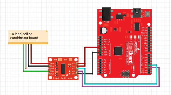
Source: SparkFun Electronics, CC BY-SA 4.0
Load cell wires
A common four-wire load cell typically has:
E+- bridge supply plus;E-- bridge supply minus;S+,A+, orO+- positive measurement signal;S-,A-, orO-- negative measurement signal.
Common color scheme:
- red -
E+; - black -
E-; - green or blue -
A+; - white -
A-.
But colors are not law. Different sensors may differ. If there is a datasheet for the specific load cell, follow it.
If the sensor has a fifth wire, foil, or shield, it is often electromagnetic shielding. Do not confuse it with a bridge measurement wire. Usually, the shield is connected to GND or housing on one side if the documentation says so, but not to measurement A+/A-.
If there is no wire diagram, do not connect the load cell "at random". First find the sensor datasheet or ring out the bridge per manufacturer guide: incorrect wires easily give unstable readings or overload the HX711 input.
Connecting HX711 to the controller
On the controller side, you usually need four lines:
VCC- module power;GND- common negative;DT,DOUT, orDATA- data;SCK,CLK, orPD_SCK- clock.
For many HX711 modules, power can be 3.3V or 5V, but check the specific module. If the controller runs on 3.3V, it is convenient to use a module and power compatible with 3.3V logic.
Pins DT and SCK can usually connect to regular GPIO. This is not I2C or SPI in the usual sense, but a simple two-wire HX711 interface.
Mechanics matter more than the circuit
A load cell must deform as the manufacturer intended.
For a beam sensor, one side usually mounts to a fixed base, the other side bears the load. If both sides are rigidly mounted to one part, the sensor will not flex normally.
Check:
- where the sensor's mounting side is;
- where the load should be applied;
- which direction the force should go;
- whether spacers are needed;
- whether the moving part clears the housing;
- no misalignment;
- no side loading;
- screws are not over-tightened;
- the spool or platform does not land past the working zone of the sensor.
For spool weight, it is especially important that all load goes through the sensor, not partly through the housing wall, axle, cable, or cosmetic cover.
Do not overload the sensor
A load cell's range is not a recommendation but a measurement limit.
If a 1 kg sensor is placed where a spool and holder can exceed this, the sensor will work poorly or permanently deform.
Choose the range with margin:
- maximum spool weight;
- holder weight;
- possible jerks;
- misalignment;
- safety margin for user error.
But too large a range is also not always good. A 100 kg sensor will sense a small spool worse than a 5 kg or 10 kg sensor with identical mechanics and electronics.
First startup
Before installing in the device, test the system on the bench:
- Connect load cell to HX711.
- Connect HX711 to controller.
- Run test code or a library.
- Ensure raw values change when you press on the sensor.
- Remove the load and check that the value is fairly stable.
- Place a known mass and check for change.
At this stage, do not demand gram accuracy. First, you need to see the sensor is alive, load direction is correct, and readings change predictably.
If the value decreases as weight increases, usually just swap A+ and A- or account for the sign in code.
Tare and calibration
A load cell without calibration does not know what grams are.
Typical process:
- Place empty platform.
- Tare: this is zero accounting for platform weight.
- Place a known mass.
- Select calibration factor.
- Check several different weights.
For filament spools, decide what counts as weight:
- entire spool with plastic;
- only remaining plastic without empty spool weight;
- weight change from initial value.
If empty spools from different makers weigh differently, accurate remainder calculation requires knowing the specific empty spool weight or working with rough estimates.
Noise and unstable readings
HX711 measures a very small signal, so the system is sensitive to noise and mechanical issues.
Causes of unstable readings:
- long wires from sensor to HX711;
- poor contacts;
- heater power wires next to signal wires;
- fan or printer vibration;
- soft base;
- play in mounting;
- temperature drift;
- load touching the housing bypassing the sensor.
Practical measures:
- keep HX711 close to load cell;
- do not run signal wires alongside heater power wires;
- secure wires so they do not pull the sensor;
- use measurement averaging;
- calibrate after mounting in housing;
- tare after device warmup if temperature notably affects readings.
What to check after assembly
Before use:
- sensor is rated for the needed weight;
- load goes through the working part of the sensor;
- fasteners do not block deformation;
- HX711 receives correct power;
DTandSCKare connected to the right GPIO;- common ground exists;
- raw values change under load;
- without load, readings do not drift too quickly;
- known mass shows expected weight after calibration;
- wires do not pull the platform;
- spool or holder does not touch the housing past the sensor.
Common mistakes
- connecting load cell directly to controller analog input;
- confusing
E+/E-andA+/A-; - trusting wire colors without datasheet;
- forgetting calibration;
- taring before final mechanical installation;
- mounting sensor so it cannot flex;
- overloading the sensor;
- choosing too large a range and losing sensitivity;
- getting instability from long wires and interference;
- expecting gram accuracy from a flexible plastic body without rigid mechanics.
Key points
- Load cell usually connects through HX711, not directly to controller.
- Sensor wires go to
E+,E-,A+,A-. - HX711 connects to controller via power, ground,
DT, andSCK. - Mechanics matter more than the circuit: load must go through the sensor correctly.
- Tare and calibration with known mass are required.
- Without rigid mounting and proper mechanics, accurate readings will not happen.
Related reading
- SparkFun: Load Cell Amplifier HX711 Breakout Hookup Guide - practical HX711 and load cell connection, wire colors,
DT/SCK, and calibration example. - SparkFun: Load Cell Amplifier HX711 product page - HX711 module description, purpose, and microcontroller interface.
- DigiKey: HX711 Datasheet by Avia Semiconductor - HX711 technical datasheet: 24-bit ADC, differential bridge input, gain, and digital interface.
- Phidgets: Load Cell Guide - practical examples of load cell mechanical installation and load application direction.
- SparkFun retired HX711 guide: load cell mechanical setup - useful illustrations of beam, button, and platform sensor mounting options.