Ligação de um Leitor RFID
An RFID/NFC reader lets you read a card, tag, or fob without wired contact.
In iDryer-like devices, this can be useful for spool identification, material profile selection, service access, or consumable tracking experiments.
Main mistake: buy an "RFID module" and assume any card will read from any distance on any controller. In reality, you need to verify frequency, tag type, interface, power, logic levels, and antenna placement.
Popular modules
Common ones include:
- RC522 / MFRC522;
- PN532;
- ready-made USB/UART RFID readers;
- NFC modules with I2C, SPI, or UART.
For simple 3D printer projects, 13.56 MHz modules and tags are most common: cards, fobs, NTAG/MIFARE-compatible tags.
What to check before connecting
Before connecting, find:
- module frequency;
- supported card and tag types;
- interface: SPI, I2C, or UART;
- supply voltage;
- logic levels;
- board pinout;
- interface selection via jumpers or solder bridges;
- read distance;
- antenna and placement requirements.
If the module is rated for 3.3V, you cannot just hook it to 5V logic without checking. Some boards have voltage regulators but lack level shifting on signal lines.
RC522: typical SPI connection
Cheap RC522 modules usually run on 3.3V and most commonly connect via SPI.
Typical lines:
VCC-3.3Vpower;GND- ground;SCK- SPI clock signal;MOSI- data from controller to module;MISO- data from module to controller;SDA,SS, orCS- SPI chip select;RST- reset;IRQ- interrupt, often unused in simple projects.
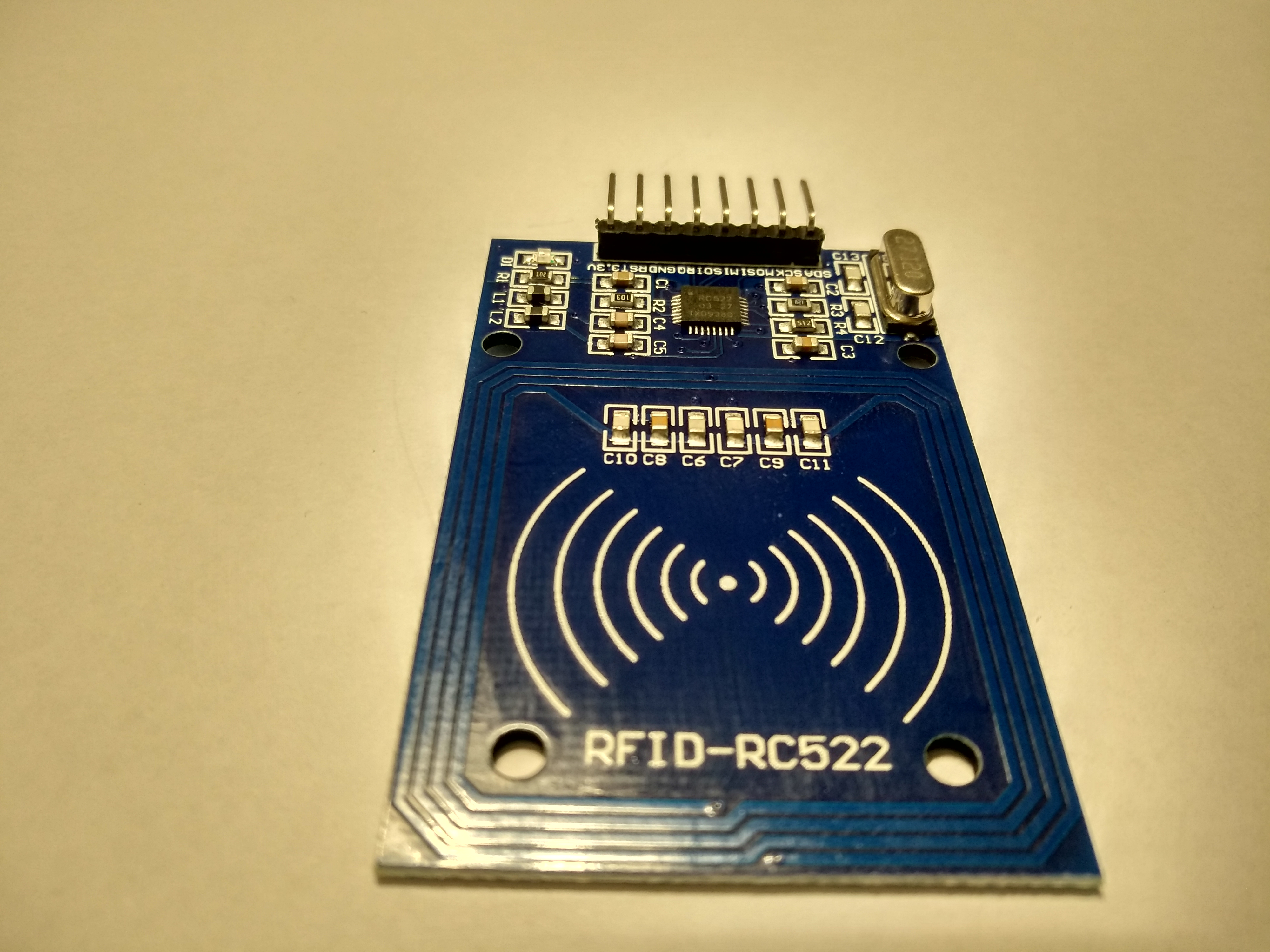
Source: Wikimedia Commons, Giacomo Alessandroni, CC BY-SA 4.0
Pin names can differ. For example, on RC522, pin SDA often means SS/CS for SPI, not the I2C SDA line. This is a common source of confusion.
PN532: SPI, I2C, or UART
PN532 is a more flexible module. Depending on the board, it can work via:
- SPI;
- I2C;
- UART.
But you cannot just connect any pins. On many PN532 boards, the interface is selected by jumpers, DIP switches, or solder bridges.
Before connecting, check:
- which interface is physically selected on the board;
- which pins match the selected interface;
- whether pull-up resistors are needed for I2C;
- whether pull-up or reset pin is needed;
- whether logic levels are compatible with the controller.
If the board says "3.3V logic", do not connect it directly to 5V GPIO.
Common ground
Like other modules, common ground is needed.
If the RFID module is powered from one source and the controller from another, their GND must be connected.
Without common ground, SPI/I2C/UART may not work or work unstably.
Tag must match the reader
RFID/NFC is not a single universal standard.
A module can physically only read tags supported by its chip and library.
Check:
- tag frequency;
- card or fob type;
- does the module support MIFARE, NTAG, ISO14443A, or the needed type;
- do you only need to read UID or also read/write data;
- does the chosen library support the needed operation.
For simple material profile selection, often reading just the tag UID and storing UID -> material mapping in firmware or host is enough.
Read distance
Read distance for small RFID/NFC modules is usually short.
Results depend on:
- antenna size;
- tag type;
- tag orientation;
- distance;
- housing plastic;
- nearby metal;
- interference;
- module power.
Metal near the antenna can drastically worsen reading. If the reader is mounted in a dryer, chamber, or spool holder, test distance in the actual assembly, not just on the bench.
Where to place the reader
For a filament spool, it is best to place the RFID/NFC reader where the user intentionally brings the tag.
Do not design logic assuming the tag will always read automatically.
Practical options:
- "bring tag here" zone on the housing;
- location near the spool holder;
- service zone for access card;
- separate panel with short read distance.
If the tag is on the spool, test with different spools, different tag orientation, different plastic, and metal proximity.
First startup
Before integration:
- Connect module on the bench.
- Run an example from the library for your module.
- Verify the card or tag reads stably.
- Record UID of several tags.
- Check that unsupported cards do not break the logic.
- Mount module in housing and retest.
At this stage, do not build complex profile systems right away. First, achieve stable UID reading.
Example device logic
For material profile, simple logic can be:
- User brings tag.
- Device reads UID.
- UID is looked up in a table.
- If UID is known, material profile is selected.
- If UID is unknown, device asks for manual profile selection.
RFID should not be the only control method. You need a manual backup: profile in menu, button, screen, or interface setting.
What to check after assembly
Verify:
- module receives correct voltage;
- logic levels are compatible with controller;
- correct interface is selected;
MOSI,MISO,SCK,CSare not swapped for SPI;SDA,SCLare not swapped for I2C;TXandRXare correctly crossed for UART;- common ground exists;
- reset/IRQ are connected as the library requires;
- tags of the right type read;
- read distance is normal in the housing;
- metal and wires do not block the antenna;
- device works normally if tag is not read.
Common mistakes
- connecting 3.3V RC522 to 5V power or 5V logic;
- confusing RC522
SDAwith I2CSDA; - forgetting
CS/SSon SPI; - swapping
MOSIandMISO; - selecting one interface on PN532 with jumpers but wiring another;
- using unsupported card type;
- placing antenna right next to metal;
- testing read distance on bench but not in housing;
- making RFID the only profile selection method;
- storing important logic only in UID without read error checking.
Key points
- RFID/NFC module must be chosen for specific tags and interface.
- RC522 usually needs
3.3Vand SPI. - PN532 can work via SPI, I2C, or UART, but interface must be selected on the board.
- Common ground is required.
- Metal near antenna can greatly worsen reading.
- For material profiles, tag UID is often enough, but manual backup selection is needed.
- Test in the actual housing, not just on the bench.
Related reading
- Adafruit: PN532 RFID/NFC Breakout Wiring - PN532 connection, SPI/I2C/UART selection, and 3.3V logic warnings.
- Adafruit: PN532 RFID/NFC guide, single page - full PN532 guide, wiring, CircuitPython, Raspberry Pi, and interface selection.
- Adafruit PN532 product page - PN532 capabilities, NFC/RFID tag support, and 3.3V UART/I2C/SPI interfaces.
- NXP: MFRC522 Standard performance MIFARE and NTAG frontend - official MFRC522/RC522 page for 13.56 MHz MIFARE/NTAG scenarios.
- DigiKey: MFRC522 Datasheet by NXP - MFRC522 technical datasheet: supported cards, power, communication interfaces with controller, and antenna/power effects on distance.