Rozhraní UART
UART is a simple serial data transmission interface between two devices. Expansion: Universal Asynchronous Receiver/Transmitter.
In practical projects, you typically hear "UART", "serial", "TX/RX", or "UART port". For beginners, the key point is: UART transmits data on the TX line, receives on the RX line, and both devices need a common GND for proper operation.
Where UART is used
UART is found almost everywhere:
- debug logs from microcontrollers;
- flashing boards via USB-UART adapter;
- host-to-MCU communication in some Klipper scenarios;
- GPS, RFID, fingerprint, and sensor modules;
- TMC stepper driver configuration;
- communication between two microcontrollers;
- service port on the board.
UART is convenient because it requires few wires and works well for simple text, command, and diagnostic exchange.
TX, RX, and GND
Minimal connection:
TX- transmission;RX- reception;GND- common ground.
TX of one device connects to RX of the other:
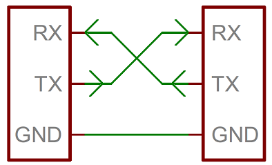
Source: SparkFun Electronics, CC BY-SA 4.0
Rule:
The most common mistake is connecting TX to TX and RX to RX. Sometimes module markings are confusing, so if there is no connection, first double-check the pinout and documentation rather than randomly changing all wires.
UART, USB, and USB-UART
UART is not USB.
A computer typically does not have bare UART pins. That's why a USB-UART adapter is needed: it connects to the computer's USB on one side and provides TX, RX, GND, and sometimes VCC, DTR, CTS lines on the other.
Examples:
- computer reading logs from a board via USB-UART;
- USB-UART flashing a board without built-in USB;
- host connecting to MCU over serial;
- adapter helping recover a board after failed flashing.
Do not confuse a USB connector on a board with UART pins on the header. On some boards USB is already connected to a built-in USB-UART chip, while on others USB goes directly to the microcontroller.
Logic levels: 3.3V, 5V, RS-232
UART describes the data transmission method, but does not guarantee safe voltage levels.
In DIY electronics, TTL/CMOS UART is most common:
3.3VUART - ESP32, RP2040, STM32, and many modern boards;5VUART - Arduino Uno/Nano and some older modules.
Applying a 5V signal to a 3.3V microcontroller input can damage the board. For incompatible levels, a level converter or other matching circuit is required.
There is also RS-232, which is separate. This is not "just UART on a DB9 connector". RS-232 has different voltage levels and different electrical logic. You cannot connect a true RS-232 port directly to a microcontroller GPIO. A level converter is needed, such as a MAX232-like circuit or ready-made adapter.
Speed and format
UART speed must match. Common values:
If the speed does not match, the terminal will show garbage or silence.
There is also transmission format. 8N1 is often used:
8- 8 data bits;N- no parity;1- one stop bit.
For most simple tasks, setting the same speed and standard 8N1 is sufficient, unless the module documentation requires otherwise.
UART in 3D printers
In 3D printers, UART often serves three different roles.
Host and board communication
Some boards can communicate with the host via serial/UART. In Klipper, this is described in the [mcu] section via serial.
TMC driver configuration
Some stepper drivers use UART to configure current, stealthChop/spreadCycle, diagnostics, and status reading. The motor itself is usually controlled not by UART, but by STEP and DIR signals.
Debug and flashing
UART can be used for logs, bootloader mode, and board recovery via USB-UART adapter.
One UART - usually two active devices
Classic UART is a connection between two devices. You cannot blindly connect multiple transmitters to one RX line.
Problems:
- two devices simultaneously pull the
TXline; - data gets mixed;
- one module receives commands intended for another;
- possible electrical conflict.
Sometimes one TX can be listened to by multiple receivers, but this is a conscious decision and not suitable as a universal rule. For beginners, it's safer to assume: one UART port - one pair of devices.
What to check before connecting
Before connecting UART, verify:
- where are
TXandRX; - is a common
GNDneeded; - logic level:
3.3Vor5V; - is this TTL UART or RS-232;
- transmission speed;
- format, if specified;
- is this UART not occupied by USB logs or flashing;
- is there another transmitter connected to this line;
- do power or only
TX/RX/GNDneed to be connected.
Power from the USB-UART adapter is only connected if it is clear the board should be powered from it. Often for diagnostics, only TX, RX, and GND are needed.
Typical mistakes
- connecting
TXwithTX,RXwithRX; - forgetting the common
GND; - applying
5VUART to a3.3Vinput; - confusing TTL UART and RS-232;
- selecting the wrong baud rate;
- connecting power from a USB-UART adapter to an already-powered board;
- using UART pins occupied by USB logs or bootloader;
- connecting multiple transmitters to one line;
- thinking UART can drive a powerful load directly.
Key takeaway
UART is a simple interface for data exchange between two devices. You need cross-connected TX/RX, common GND, matching speed, and compatible logic levels.
UART is not a power supply and does not work as a power output. It transmits data, not spin motors or activate heaters directly.
Related materials
- SparkFun: Serial Communication - good practical explanation of UART, TX/RX, baud rate, TTL serial, RS-232, and common mistakes.
- SparkFun: Serial Communication - UARTs - what UART does inside a microcontroller and why TX/RX are needed.
- Adafruit: Serial UART on FT232H - example of a USB-UART adapter and connecting TX/RX/GND to a serial device.
- SparkFun: Serial Basic CH340C Hookup Guide - example of a USB-UART adapter, RX/TX/VCC/GND pins, and loopback test.
- Klipper: Configuration reference -
[mcu]- how serial MCU connection is described in Klipper configuration.