Řadič ESP32
ESP32 is a family of Espressif microcontrollers with Wi-Fi, Bluetooth, and a large set of peripherals. In DIY devices, it is often chosen when you need to build a standalone module: it connects to the network itself, reads sensors, shows a page in a browser, and controls simple outputs.
For devices around a 3D printer, ESP32 is useful not as "another power board," but as a small networked controller: a temperature/humidity sensor, a ventilation module, a simple filter with a web interface, separate camera monitoring, or a standalone dryer.
Where ESP32 is useful
Typical tasks:
- Wi-Fi temperature and humidity sensor;
- separate fan controller via MOSFET module;
- controlling a relay or SSR with a low-voltage signal;
- OLED display over I2C;
- RFID/NFC reader over SPI or UART;
- servo with separate power;
- simple web page for status and settings;
- integration with MQTT, Home Assistant, or your own local logic;
- autonomous prototype that does not need to be part of Klipper.
ESP32 is good when the device should live separately from the printer and exchange data over the network. If the task is simply to add pins to Klipper, it is usually better to look at RP2040, STM32, or a ready-made printer board.
Typical device architecture
ESP32 does not power loads directly. It outputs control signals, and separate modules do the power work.
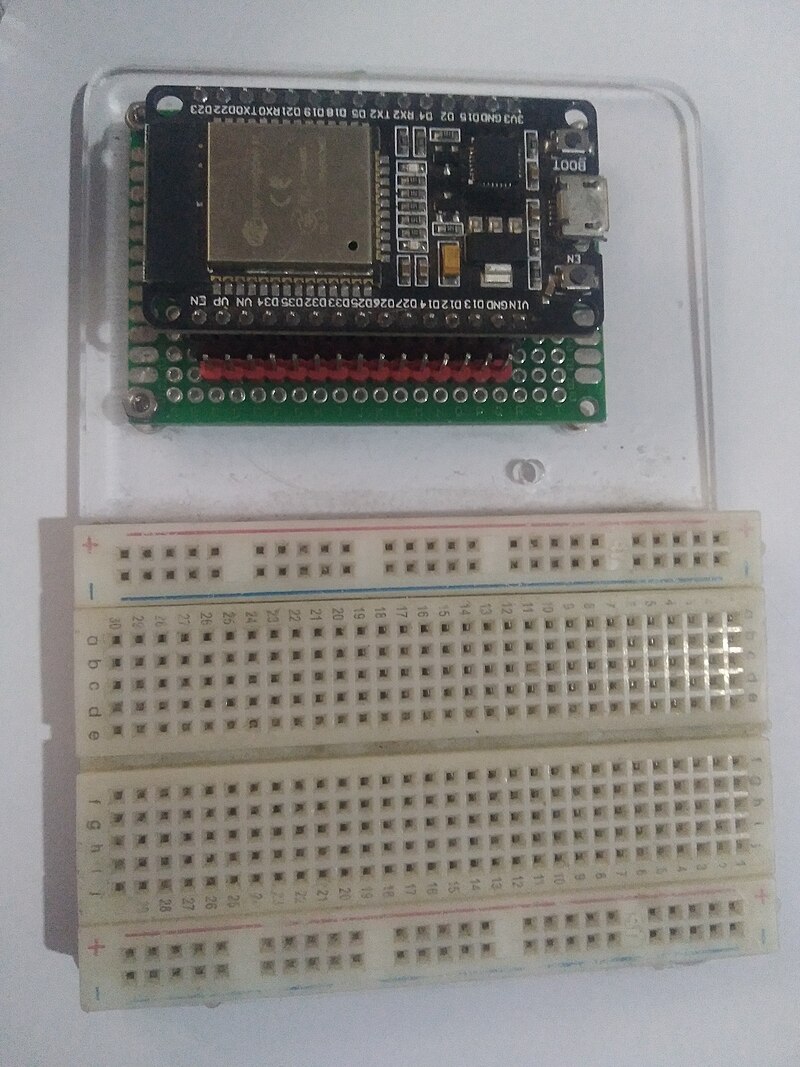
Source: Wikimedia Commons, Edwiyanto, CC BY-SA 4.0
In practice, this looks like:
- ESP32 is powered from USB or stable
5Von the development board; - the ESP32 logic itself runs on
3.3V; - sensors are connected to GPIO, I2C, SPI, UART, or ADC;
- fans, LED strips, DC heaters are connected via MOSFET or driver;
- network heaters are connected only through an appropriate AC SSR/relay and a safe power section;
- servo is powered from a separate
5V/6Vsource, and ESP32 provides only the signal.
GPIO is not a power source for a load. A pin can switch the driver input, but should not power a fan, heater, relay, servo, or LED strip directly.
What ESP32 means on a board
The label "ESP32" can mean different things:
- the ESP32 chip itself;
- a module with the chip, flash memory, and antenna, such as ESP32-WROOM;
- a dev board with USB, power regulator, buttons, and exposed pins;
- newer variants: ESP32-S3, ESP32-C3, ESP32-C6, and others.
For a first project, it is more convenient to use a dev board than a bare module. A dev board already has USB, a power regulator, BOOT/EN buttons, and pins for breadboarding.
Before buying, check:
- the exact board and chip name;
- whether it has USB-C or micro-USB;
- which USB-UART or built-in USB is used;
- whether there is a schematic and pinout;
- which GPIO are really exposed;
- what power regulator is on the board;
- whether it has a proper antenna and space around it;
- whether the board size fits your enclosure.
3.3V logic
ESP32 works with 3.3V logic. This means that a typical HIGH level on GPIO is about 3.3V, not 5V.
What matters:
- do not apply
5Vto ESP32 GPIO; - for
5Vsensors and modules, you may need a level converter; - I2C pull-ups should go to
3.3Vif the bus is connected to ESP32; - some ready-made MOSFET/SSR modules may not work reliably from
3.3V; - load power cannot be taken from GPIO.
Many sensors are already available in 3.3V variants. For ESP32, this is the best choice.
Power
Dev boards usually have a USB input and a 5V/VIN pin, and the ESP32 itself is powered by a 3.3V regulator.
Common mistakes:
- powering ESP32 from a weak USB cable;
- powering a servo, fan, or relay from the
3.3Vpin on the board; - connecting a heavy load to the
5Vpin without understanding where that current comes from; - not connecting common GND between ESP32 and the low-voltage driver;
- ESP32 resets when Wi-Fi starts due to power sag.
Wi-Fi draws pulsed current. For stable operation, a good cable, regulator, capacitors on the board, and separate power for loads are important.
GPIO and special pins
ESP32 has many GPIO, but not every pin is equally convenient.
On classic ESP32:
- some pins are tied to chip loading, these are strapping pins;
GPIO6-GPIO11are usually occupied by flash memory and are not used;GPIO34-GPIO39are input-only;GPIO1andGPIO3are often used as UART for firmware and logs;- some pins may be occupied by LED, button, or other circuits on a specific dev board.
Strapping pins determine the boot mode at startup. If external circuitry pulls such a pin the wrong way, ESP32 may not boot or may enter firmware update mode.
Practical rule: for the first version, use pins from the pinout of your specific board and avoid pins marked BOOT, FLASH, STRAP, TX0, RX0, GPIO6-GPIO11 unless you understand their role.
ADC on ESP32
ESP32 can measure analog voltage via ADC, but it is not a laboratory multimeter.
What matters:
- on classic ESP32 there are ADC1 and ADC2;
- ADC2 conflicts with Wi-Fi, so for a Wi-Fi device it is better to use ADC1 pins;
- the measurement range depends on the attenuation setting;
- measurement may require calibration;
- you cannot apply voltage above the GPIO safe level to ADC;
- a thermistor usually needs a voltage divider and the correct table/model in firmware.
If you need an accurate temperature sensor, it is often simpler to use a digital sensor or a ready-made module with a known library. For an NTC thermistor, ESP32 works, but the circuit and ADC settings must be checked.
PWM, I2C, SPI, and UART
ESP32 is convenient for peripherals:
- PWM via LEDC is suitable for fans, backlighting, and servo signals;
- I2C is suitable for OLED displays and many sensors;
- SPI is suitable for RFID modules, displays, and fast devices;
- UART is suitable for GPS, some sensors, other controllers, and debugging.
ESP32 has a flexible GPIO matrix: many signals can be assigned to different pins. But this does not mean any pin is always a good choice. Specific board limitations, flash memory, boot pins, and occupied UART still need to be considered.
ESP32 and Klipper
ESP32 is better viewed as a separate Wi-Fi/IoT device near the printer, not as the main path for an additional MCU in Klipper.
Klipper is organized as a host plus one or more MCUs. For new additional MCUs, it is usually more practical to use:
- RP2040;
- STM32;
- ready-made 3D printer boards.
ESP32 can exchange data with the printer system separately: via MQTT, HTTP API, Home Assistant, your own server, or another integration. But this is no longer the same as adding [mcu] to the Klipper configuration and using pins directly.
What to check before buying
Before buying an ESP32 board, check:
- exact model: ESP32, S3, C3, C6, etc.;
- logic voltage;
- whether it has USB and how the board is flashed;
- whether there is an official pinout or schematic;
- which pins are safe for GPIO;
- which pins are input-only;
- which pins are occupied by flash/PSRAM, USB, UART, or LED;
- whether you have enough ADC/I2C/SPI/UART for the task;
- how the board is powered;
- whether it fits in the enclosure;
- whether there is a library or firmware for your scenario.
If a board from a marketplace does not have a schematic and a proper pinout, it can be used for experiments, but is not suitable for a device that needs to run unattended for a long time.
Common mistakes
- applying
5Vto ESP32 GPIO; - powering a load from GPIO;
- powering a servo or relay from a weak
3.3Vpin; - forgetting common GND with MOSFET/driver;
- choosing an ADC2 pin for a sensor and then enabling Wi-Fi;
- using a boot strapping pin so that ESP32 does not start;
- using
GPIO34-GPIO39as outputs; - buying a module without a pinout and schematic;
- thinking that "ESP32 with Wi-Fi" automatically means safe network heater control;
- trying to replace power electronics with firmware.
Key points
ESP32 is a good choice for autonomous Wi-Fi devices: sensors, web interfaces, simple ventilation control, filters, displays, and peripherals.
But ESP32 works with 3.3V logic, has special pins, and should not directly power loads. For power circuits, MOSFET, drivers, relays, or SSRs are needed, and for a network heater, a complete safe power section is needed.
Related materials
- Espressif: ESP32 Wi-Fi & Bluetooth SoC — official overview of the ESP32 family, modules, dev boards, and links to documentation.
- Espressif: ESP32 Series Datasheet — chip characteristics, peripherals, ADC, PWM, UART, I2C, SPI, and pin limitations.
- ESP-IDF Programming Guide: GPIO & RTC GPIO — GPIO table, strapping pins, input-only pins, flash/PSRAM pins, and ADC2 limitation with Wi-Fi.
- Espressif: ESP32 Hardware Design Guidelines — recommendations for power, strapping pins, GPIO, ADC, and board design.
- Arduino-ESP32: LED Control API — PWM/LEDC in Arduino-ESP32 for fans, backlighting, and other PWM signals.
- Klipper: Code overview — Klipper architectural context for MCU and list of supported micro-controller backends in the source tree.