USB-TTL
A USB-TTL adapter, or USB-UART adapter, lets your computer talk to a microcontroller over UART through USB.
You need it for:
- flashing some boards;
- reading logs;
- debugging UART communication;
- configuring modules;
- recovering a board when regular USB doesn't work;
- connecting to a device without built-in USB-UART.
Common adapters use chips like CH340, CP2102, FT232 and similar.
USB-TTL or USB-UART
Consumer descriptions often say USB-TTL.
Technically it usually means a USB-UART adapter with TTL logic levels.
The main thing to understand:
- USB side connects to the computer;
- UART side connects to the microcontroller;
- the adapter is not a programmer for all boards;
- the adapter does not replace ST-Link if you need to flash STM32 through SWD.
Main pins
Typically there are:
GND;TX;RX;VCCor3V3/5V;- sometimes
DTR; - sometimes
CTS,RTS.
Minimum for communication:
GND;TX;RX.
Power is only connected if you are certain the adapter should power the board.
TX and RX are cross-connected
UART is connected like this:
TX is transmit.
RX is receive.
The transmitter of one device must connect to the receiver of the other.
If you connect TX to TX, communication usually won't work.
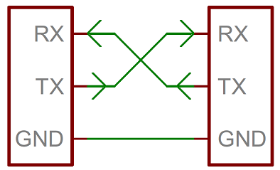
Source: SparkFun Electronics, CC BY-SA 4.0
Common ground
The adapter GND and board GND must be connected.
Without a common ground, UART may not work or will work unstably.
Even if the board is powered from a separate power supply, ground is still needed as the common signal level.
3.3V and 5V logic levels
This is one of the most important points.
The adapter can work with logic at:
3.3V;5V;- switchable
3.3V/5V.
Many modern boards and modules use 3.3V logic: ESP32, RP2040, many STM32.
If you apply a 5V UART signal to a 3.3V input, you can damage the pin or the entire board.
Before connecting, verify:
- what logic level the board uses;
- what logic level the adapter uses;
- what the 3.3V/5V jumper does;
- whether the jumper changes only the
VCCpower or also theTX/RXlevels.
Some adapters provide 5V power but 3.3V logic signals. Others change both power and levels. Check the specific adapter documentation.
Power from adapter
You don't always need to connect VCC.
Often it is safer to connect only:
GND;TX;RX.
Power the board from its normal source.
You can connect VCC from the adapter if:
- the board is rated for that voltage;
- the board current is within the adapter capability;
- there is no other power at the same time;
- the board documentation allows powering through this pin.
A dangerous mistake is supplying power from both the USB-UART adapter and a separate power supply at the same time, causing the sources to conflict.
DTR and auto-reset
Some boards use DTR for automatic reset during flashing.
For example, Arduino Pro Mini and similar boards can use DTR through a capacitor for auto-reset.
If flashing doesn't start automatically, it might be because:
- DTR is not connected;
- manual reset is needed;
- the wrong adapter is selected;
- the wrong bootloader is selected;
- the speed or board in the IDE is selected incorrectly.
For simple log reading, DTR is usually not needed.
How to check if the adapter is visible to the system
On macOS and Linux, the adapter usually appears as a device in /dev.
Examples:
On Windows it appears as a COM port.
If the port doesn't appear:
- check the USB cable;
- try a different USB port;
- check the driver;
- verify it is not just a charging cable;
- see what chip is on the adapter: CH340, CP2102, FT232.
Cheap adapters sometimes require a separate driver, especially on Windows.
Loopback test
Simple way to check the adapter:
- Connect the adapter's
TXandRXtogether. - Open a serial terminal.
- Select the port and speed.
- Type text.
If the characters you type come back, the adapter and port probably work.
After the test, remove the jumper between TX and RX.
Common errors
TXconnected toTXandRXtoRX;- forgot common
GND; - selected 5V level for a 3.3V board;
- connected
VCCeven though the board is already powered separately; - USB cable turned out to be charging-only;
- CH340/CP210x/FTDI driver not installed;
- wrong COM port selected;
- UART speed doesn't match;
- expecting USB-UART to flash STM32 through SWD;
- confused boot mode or reset during flashing.
The essentials
- USB-UART adapter is needed for UART communication between computer and board.
- Minimum for communication:
GND,TX,RX. - Adapter
TXgoes to boardRX, adapterRXgoes to boardTX. - Check 3.3V/5V logic levels before connecting.
VCCis only connected if you definitely need power from the adapter.- If the adapter is not visible, check the cable, driver and USB port.
Reference materials
- SparkFun: Serial Basic Hookup Guide - USB-to-serial adapter, TX/RX/GND, VCC, DTR and 3.3V/5V switching.
- SparkFun: Serial Basic CH340C Hookup Guide - modern CH340C USB-UART adapter, pins, LEDs and voltage selection.
- SparkFun: Serial Communication - UART basics, TX/RX and serial communication.
- Silicon Labs: CP210x USB to UART Bridge VCP Drivers - official CP210x Virtual COM Port drivers.
- Adafruit FTDI TTL-232 USB Type C Cable - example cable with 5V power and 3.3V logic, showing why power and signal levels need to be read separately.