SPI Interface
SPI is a fast serial communication interface between a controller and peripheral devices. Expansion: Serial Peripheral Interface.
SPI is often used where data needs to be transmitted faster than I2C, or where the device is designed for SPI: display, SD card, RFID module, sensor, driver, or memory chip.
Where SPI is used
In 3D printers and iDryer-like devices, SPI may appear in:
- RFID/NFC modules like RC522;
- OLED/TFT displays;
- SD cards;
- accelerometers for input shaper;
- stepper drivers, for example TMC2130/TMC5160;
- memory chips;
- ADC/DAC and expansion boards;
- some sensors and specialized modules.
SPI is usually faster than I2C, but requires more wires and more careful pin selection.
Basic lines
A typical SPI uses:
SCKorCLK- clock signal;MOSI- data from controller to device;MISO- data from device to controller;CS,SS, orNSS- select specific device;GND- common ground;- module power.
Diagram with two devices:
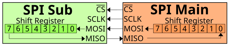
Source: Wikimedia Commons, Em3rgent0rdr, CC0 Public Domain
SCK, MOSI, and MISO can be shared by multiple devices. But each device usually needs its own CS.
CS instead of addresses
In I2C, devices are distinguished by addresses. In SPI, there are usually no addresses. The controller selects the device with a separate CS line.
Example:
SCK  -> common to all SPI devices
MOSI -> common
MISO -> common
CS1  -> RFID module
CS2  -> display
CS3  -> SD card
When the controller wants to talk to the RFID module, it activates CS1. When it wants to talk to the display, it activates CS2.
Most commonly, CS is active low: at rest the line is HIGH, to select a device - LOW. But this needs to be verified in the technical datasheet.
MOSI/MISO and new names
In old and very common schemes, the names are:
MOSI- Master Out Slave In;MISO- Master In Slave Out;SS- Slave Select.
In newer documentation, you may see neutral names:
PICO- Peripheral In Controller Out, equivalent to MOSI;POCI- Peripheral Out Controller In, equivalent to MISO;CS- Chip Select.
In 3D printer electronics, MOSI, MISO, SCK, CS are still very common. The main thing is to understand signal direction and check the pinout of the specific module.
MISO may not be needed
Not every SPI device actually sends data back.
For example, a simple display may only receive commands and pixels. Then the MISO line may be missing or unused.
But for devices that read data, MISO is needed:
- RFID module;
- SD card;
- sensor;
- driver with diagnostics;
- memory chip.
If the module is supposed to respond and MISO is not connected or mixed up, initialization may fail.
SPI speed and mode
SPI has a speed. It can be much higher than I2C, but that does not mean you need to set maximum immediately.
Work is affected by:
- wire length;
- ground quality;
- module and its datasheet;
- noise level;
- controller frequency;
- chosen SPI mode.
SPI mode is set by clock polarity and clock phase parameters: CPOL and CPHA. Mode 0 is often used, but not always. If the mode is wrong, the device may not respond or return incorrect data.
In most ready-made libraries, the mode is already set. But if you are connecting an unusual module or writing low-level configuration, you need to check the datasheet.
3.3V and 5V
Like other interfaces, SPI does not guarantee safe voltage levels.
ESP32, RP2040, STM32, and many modern modules operate with 3.3V logic. Arduino Uno/Nano often uses 5V.
Before connecting, verify:
- module power;
- logic level of
SCK,MOSI,MISO,CS; - if there is level matching;
- if the module tolerates
5Von signal inputs; - if the controller input tolerates
5V.
For example, RC522 typically requires 3.3V power and logic. Connecting it to a 5V Arduino without level matching is a bad idea.
SPI in Klipper
In Klipper, SPI is used for various devices: TMC drivers, accelerometers, some displays, and sensors.
Configuration may include:
cs_pin- device select pin;spi_bus- hardware SPI bus;spi_speed- speed in Hz;spi_software_sclk_pin;spi_software_mosi_pin;spi_software_miso_pin.
If the device is connected to an additional MCU, the pins should belong to that MCU. As with other Klipper sections, the specific board pinout is more important than guesses.
Rough idea:
[some_spi_device]
cs_pin: chamber:gpio9
spi_software_sclk_pin: chamber:gpio10
spi_software_mosi_pin: chamber:gpio11
spi_software_miso_pin: chamber:gpio12
This is not a ready config for a specific device, but an illustration: all SPI pins must be on the MCU to which the module is actually connected.
Wire length and interference
SPI can work fast, but does not like long, sloppy wiring.
Practical rules:
- keep
SCK,MOSI,MISO,CSshort; - route near
GND; - do not route parallel to heater and motor wires;
- reduce
spi_speedif there are errors; - use proper connectors;
- do not pull SPI across the entire printer without reason;
- for remote nodes, more often choose CAN, UART/RS-485, or a separate MCU near the module.
The SCK line is especially sensitive: it is a clock signal. If it is dirty, all communication can become unstable.
SPI and RC522
RC522 is a good example of an SPI module with naming confusion.
On many RC522 boards, the SDA pin is actually used as SS/CS for SPI. This is not I2C SDA.
For RC522, you typically need:
3.3V;GND;SCK;MOSI;MISO;SDA/SS/CS;RST;- sometimes
IRQ, but in simple projects it is often not used.
A detailed diagram is in the practical article: Connecting an RFID reader.
What to check before connecting
Before connecting an SPI module, verify:
- module power;
- logic level;
- pinout of the specific board;
- where are
SCK,MOSI,MISO,CS; - if
RST,DC,IRQ, or other pins are needed; - which
CSis assigned to the device; - if
CSdoes not conflict with another module; - if hardware SPI or software SPI is needed;
- what speed the documentation recommends;
- if the firmware supports this module.
Typical mistakes
- mixed up
MOSIandMISO; - forgot
CS; - connected two devices to one
CS; - did not connect common
GND; - applied
5Vto a3.3VSPI module; - mistook
SDAon RC522 for I2CSDA; - selected too high a speed;
- made wires too long;
- connected the module to one MCU, but specified pins from another;
- think SPI is a power interface to drive load.
Key takeaway
SPI is a fast interface for modules near the controller. Usually you need SCK, MOSI, MISO, CS, power, and GND.
The main difference from I2C: SPI usually has no addresses, and each device is selected by a separate CS. Before connecting, verify pinout, logic levels, speed, wire length, and firmware support.
Related materials
- SparkFun: Serial Peripheral Interface - practical explanation of SPI, data lines, new PICO/POCI names, and basic exchange logic.
- SparkFun: SPI Chip Select - why
CSis needed and how to connect multiple SPI devices. - Adafruit: SPI Devices - SPI vs I2C comparison, separate
CS, speed, polarity/phase, and limitations. - DigiKey: SPI Simplifies Device Communication - options for connecting multiple SPI devices and role of
CS. - Klipper Configuration Reference: Common SPI settings -
spi_speed,spi_bus, software SPI, andcs_pinparameters in Klipper.